


- Category: Campervan
- Written by Paul Chubb
- Hits: 624
Cleaning up the vehicle electrics

With any vehicle there are always a number of things that could be done to improve the experience. With an old vehicle – Tin Lizzy is 25 years old – there were a mix of things that she never had and things that no longer work. This last week I spent working on various electrical items in the cabin. I replaced an immobiliser, a stereo head unit and fixed a dome light. I also did the investigation and planning for a new switch for the heater fan and and a buzzer to indicate the headlights were left on.
Stereo Head Unit
Tin Lizzy came with a single Din stereo head unit that was cabled to two computer speakers. The CD player on it didn't work, no bluetooth and the radio only picked up one station reliably. I wanted to replace it for better music options but also to implement a reversing camera. I had a double Din unit that had all the features and many more than I wanted.
The first challenge was to remove the console fascia. This is in one piece that goes from the radio area across behind the steering wheel and around the instruments. There are two screws above the instruments but the rest just snaps in. Carefully lever it out following the direction from the loosened to the tight.
Once it is loose you can kind of prop it up out of the way over the steering wheel without need to remove much of the wiring apart from the loom that attaches to the hazard warning switch.

At a minimum you will probably have to connect 7 wires: 2 for each speaker, 12v continual, 12v switched by accessory and ground. I soldered all these. You will also need to plug in the aerial cable which is a different type of plug.
I did this but found that the head unit didn't start. Had a bad time for a minute thinking that the unit was dead. It had been sitting in a draw for a few years. I began trouble shooting, checking the amount of current and the ground cables and found that the 12v continual cable had no charge on it. This was probably one reason the old head unit failed to work well. I ran a new cable and it fired up immediately.
The hardest two parts were to mount the brackets that hold the head unit. For some reason, the brackets are asymmetrical on the Hiace with the right bracket much further into the console than the left. The second problem was that the head unit didn't fit the hole in the console. I had to butcher the plastic below the head unit to drop it a mm or two. I then had to take a file to the surround to make it big enough to fit over the head unit.
Today I finally have music that I choose in the cab of Tin Lizzy.
{… To be continued (reversing camera) …}
Immobiliser
Tin Lizzy originally came from Western Australia which requires the fitting of an engine immobiliser by law. This was to reduce the number of vehicle thefts. Tin Lizzy was fitted with a jack plug style immobiliser and when purchased, there was only one jack plug. I failed to find additional jack plugs for sale, and so fairly early on, I decided to replace it.
There are two main reasons that vehicles are stolen: if they are newish and valuable for parts or resale and by kid joy riders. Tin Lizzy certainly isn't in the first category. However who knows what kids will do. The value of the interior fittings will approximately double the replacement cost of the van and so it is worth providing some disincentive to a thief. At the same time I wanted something simple and easy to install.
The big difference between immobilisers for the older car, is the number of things that they disable. The more things they disable, the more things that a thief has to re-enable to steal the vehicle. In my case I purchased one that disabled two systems.
On petrol based cars, there are lots of systems that can be used to immobilise the engine: ignition, coils, fuel pump and starter motor. Diesel engines tend to be much harder. If you disable the glow plugs, the engine may still start and run. The original diesels were started by simply supplying oil to hot cylinders. Equivalent issues are evident if you disable the starter motor.
The main way to disable an engine used on diesels is to disable the flow of fuel. Some diesels have an electronic shutoff valve as part of the injector and fuel rail assembly. Others have electric injector fuel pumps that can be disabled. Still others have a mechanical injector fuel pump. These last have no electrical circuits to hack. You can buy a solenoid activated valve that can be inserted into a fuel line. In fact some old diesel owners used to install a manual tap to disable their vehicles by hand. I didn't try the solenoid route, I may get to it another time.
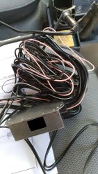
The immobiliser had the following wires coming off it:
|
Label |
Purpose |
|
+30g |
Constant 12v power |
|
+15g |
Switched 12v power that is only on when the ignition is on. |
|
Gnd x 2 |
Ground leads to go to different chassis connection points |
|
1 x 2 |
First set of control leads |
|
2 x 2 |
Second set of control leads |
|
Leads to connect the jack plug socket |
Various leads that were the only ones not black |
Because I was replacing an existing immobiliser, I started at its jack plug socket and followed the cable back to find the box. This was soon found. I then followed the cables from the box – all of them black and identified them against the wiring diagramme for Tin Lizzy.
The control wires on the immobiliser are essentially relays that are normally open. When the immobiliser is disarmed using the jack key, these close allowing the engine system to work. On my immobiliser, these relays will only handle a maximum of 10amps.

There are two ways to wire the control wires into the car so that they disable the chosen system. If the system runs at less than 10a current, then you simply break a wire – usually the power side because most things sink the current straight into the chassis rather than having a ground lead – and connect each of the resulting ends to a control wires. My instructions said to remove at least 30mm of the wire.
The other way – I didn't use this method – is to connect a normally open (NO) relay into the wire of the system to be disabled. The control wire on the immobiliser: one side goes to positive 12v and the other to the relay activation coil. On the other side of the coil, connect to ground. This will mean that when the immobiliser is disabled, the relay will fire as it gets 12v of current.
I have largely gone off the crimp style connectors. I especially don't the splice connectors that allow you to join the middle of two wires together – they are always problematic. For this work, I soldered the connections and covered the joins with heat shrink which gives a very neat finish.
Overall it took me about half a day to replace the immobiliser, however a lot of that was spent trying to figure out which systems to hack.
Dome Light
A few weeks ago I discovered a funny plastic mold wrapped around my rear view mirror with a switch coming out of it. I eventually figured it for a deformed dome light. It didn't work, so I replaced the bulb. This got it working with the door open but not on the other setting of always on. It is less than useful trying to read a book with the door open on a cold night...
The connection to this light is very simple. It has two wires connected to the switch one carrying continual 12v and the other 12v when the door is open. The other side of the circuit simply sinks the current into the chassis.
I fiddled around with the light, including removing the whole light and mirror assembly. When I screwed the assembly back on it started working properly. I guess that the ground connection was a bit dodgy.
Fan Control

Like many vehicles of this age, Tin Lizzy came with a sliding fan switch that had five positions including off. The switch chooses the length of a string of resistors in serial. The one on Tin Lizzy had failed some time in the past and was replaced with a simple toggle switch that was wired to supply power directly to the heater fan. This gave only the top fan speed. I wanted to restore the different fan speeds.
The first step was to check the resistor pack to see if it still worked. It is the next most likely thing to fail after the switch. The resistor pack is located behind a kick panel directly under the glove box. It is inserted – like most resistor packs – into the air duct to be kept cool by the air from the fan. The front of the pack has a four way spade plug on it. Each terminal connects to a position between the three resistors in the pack and before or after the resistor string. Checking the resistance between each of the terminals produced the expected range of resistances up to about 2 ohm.
With the resistor pack checking out ok, I knew that if I could find a suitable rotary switch, I could replace the toggle switch and get the original speeds with little extra wiring. The problem is finding a switch that will handle the load while still being small enough to be easily installed. Car auto-electrics tend to be chunky and primitive. However it can be hard to find components that will take the loads used. A rotary switch from somewhere like Jaycar will switch something like 200ma. I could wire in four relays but that sounded expensive and could end up a dogs breakfast. I decided to source a switch from another car.
The first step is to identify the amount of current drawn by the fan motor. This is harder than it sounds. The best indicator is the size of the fuse for the motor. On Tin Lizzy this is 40a. The next step is to find a car with a rotary switch that has a fuse that is the same amperage or higher. I searched ebay for a car fan switch. After a couple of hours on ebay and the internet, I had three contenders. I then chose the switch that looked to be the easiest to mount – ie room for two screws on the collar to tie it back to the console.
Update
The rotary switch eventually arrived. The hardest part was then mounting the switch. Two self tapping screws sorted that. The wiring was simply a matter of running a series of wires - 6mm2 rated at 50A - with female spade connectors down to the resistor. I then ran wire from the resistor to an earth point on the chassis and a power cable from the ignition switch assembly to the rotary switch. The final thing was to mount a knob on the switch. The spindle didn't project far enough. I used a micro spray irrigation riser - essentially black narrow tube - to make an extension. This was super glued into the knob and the other end made a tight fit over the spindle.
Headlight Buzzer

After the first time I had a flat battery because of leaving the head lights on, and the pain of trying to jump start it, I decided to add a buzzer. A long time ago I had a car that I wanted to add a headlight buzzer to. I bought a kit and discovered it to be a simple piezo buzzer and instructions to wrap the wire around two fuses.
There are a few different recipes out on the internet on how to add a buzzer. Some use a relay but I decided to use the same method on the KISS basis. I have ordered a piezo buzzer. Tin Lizzy has blade fuses. I also added some fuse piggy backs to the order that allow you to add circuits.
Update
I bought some fuse taps but when I went to use them found that they were the wrong size. Not wanting to waste more time getting more, I proceeded to wire in the piezo buzzer. A piezo buzzer is very like a diode. It allows current to flow in only one direction. This means that if you provide the same voltage on both sides no current with flow and the buzzer will remain silent. If you remove the voltage on the output side then the buzzer will sound.
On this basis you need to indentify two fuses. One fuse needs to have voltage on it when the ignition is on. This has the output side connected to it. You also need to find a fuse controlling the lights. Best case would be to have one controlling the parkers since these are switched on first and off last. In my case, I only had two fuses, one for each of the headlights. The output side, I used the fuse marked "engine".
To attach the wire, I simply stripped it and wraped it around one blade of the fuse. This works find
